Electronics
Here are some descriptions of the electronics I have in use:
- Basics
- Simple electronic
- Electronic for two bulbs
- PWM
- Simple Softstart
- Simple anti-deep-discharge (6V)
- Microcontroller controlled electronics
- DC-DC-converter
- Charger (reconstruction)
- Charger, as I want it (lead-acid)
- back to homepage
The file format I used is WMF - Windows Metafile Format. Nearly all Windows programs can import it (e.g. WINWORD, EXCEL, AMIPRO, CorelDraw...).
Basics
Many people just use simple relais to switch the bulb current. This plan is from the french light described at another page. ILS is a reed contact.
Because the current is very high in the switching phase that means a hard time for the bulb. The first circuit which handles that I found in the magazine elrad 2/89 (only in German, with circuits). My circuits are similar to this one.
This is the block diagram: (the two moduls "AccuCheck" and "Storage and Flash Signal" are missing in the simple circuit)
The halogen bulb is switched by a MOSFET transistor and stays connected to the battery voltage. If the reed contact is closed, the rest of the circuit gets power. The voltage controller IC 7805 supplies the supply voltage for some ICs and the reference voltage for the comperators. The modul "AccuCheck" contains 2 comperators which set a signal if the battery voltage sinks below a certain adjustable value. The modul "Warning" shuts off the light in regular intervals to warn the diver. If the voltage drops even more the signal "OFF" is set and the light switched off.
The modul "Storage and Flash Signal" generates the flashing signal and stores the occurence of "Warning" and "OFF". That is necessary because the battery voltage rises if the light is switched off, and the light would be switched on again.
The modul "OP and MOSFET Current-Control" is a switchable, adjustable current source, which limits the current to 1,5x of the nominal value.
Simple Electronics
 The
simplest and smallest circuit I use is not much more than a relais with
a current control (picture) (circuit-WMF-Format)
(all WMF-files as PDF) (GIFs
of the Layout). It is smaller than most relais and can switch up to
4A, with a cooling device perhaps more. One version is slim and has parts
on both sides. The other one is wider but narrower.
The
simplest and smallest circuit I use is not much more than a relais with
a current control (picture) (circuit-WMF-Format)
(all WMF-files as PDF) (GIFs
of the Layout). It is smaller than most relais and can switch up to
4A, with a cooling device perhaps more. One version is slim and has parts
on both sides. The other one is wider but narrower.
There is a possible variation to this and the following circuit. If you want to decrease the voltage drop across the MOSFET and therefore the temperature rise, too, you can put a second MOSFET in parallel to the first one. You connect the pins with each other; that's easyily accomplished as piggyback(?). To be absolutely on the safe side you could use seperate GATE-resistors. To adjust the higher current (>7A) it's necessary to change the resistors at the (+) input of the comparator or put another 0,01Ohm resistor in parallel to the first one.
Look at these improvements, too.
Electronics for two bulbs
 The
more complicated circuit contains the current control for two bulbs and
a two-step voltage control for the battery (circuit-WMF-Format)
(all WMF-files as PDF) (GIFs
of the Layout). I prefer lights with two switchable reflectors. All
these diodes are necessary to control both bulbs with one seperate reed
contact without affecting the voltage control. Only the modul "OP
and MOSFET" needs to be in duplicate.
The
more complicated circuit contains the current control for two bulbs and
a two-step voltage control for the battery (circuit-WMF-Format)
(all WMF-files as PDF) (GIFs
of the Layout). I prefer lights with two switchable reflectors. All
these diodes are necessary to control both bulbs with one seperate reed
contact without affecting the voltage control. Only the modul "OP
and MOSFET" needs to be in duplicate.
If you need only one bulb you can use this version (circuit-WMF-Format) (all WMF-files as PDF).
Attention !!! I'm sorry but there is
an error in the circuits, which can lead to problems with reed contacts.
Connect a resistor of about 10 Ohm in series with D1 (the diode which feeds
the big 470uF capacitor C1) or if you can't get there in series with L1R1
and L2R1 (switching inputs). If that't not the case there will be a high
load current to the capacitor when switching on, that may lead to a "glued"
reed contact.
You may exchange the BUZ 11 against a BUZ12AL, which has a lower On-resistance.
Another improvement can be achieved by putting a capacitor of 47nF (10-100nF)
between GATE of the MOSFET and ground. You won't see a difference in use,
but the current waveform during the current-limiting-phase will be much
smoother. If you are using a PWM dimmer, too, the capacitor should have
only 4,7nF.
This circuit will draw about 35mA of current.
PWM
This circuit is used to dimm the output current if one of the pins PWMx
is connected to 12V. It can easily be added to the circuit above. The transistor
can be almost every NPN type (e.g. BC547).
One application is the connection of a 12V bulb to a voltage source
with 14,4V (12x NiCds). But be sure to measure every voltage drop before
using a dimmer. E.g. my 6th accumulator with 12 cells should have 14.4V
theoretically. When connected to a load there are only 13.8V left due to
cables and inner resistance. At the lighthead there are only 13V, which
is just right for a normal halogen bulb.
Even 14.4V would work. HLX bulbs for 12V do just the same. But be sure
not to connect HLX bulbs to 14.4V, which would destroy them.
This circuit will draw about 30mA of current.
There are two projects for the future:
a) a complete lamp control including SOS and perhaps a charging control in one PIC microcontroller
b) a modular system based on a switching unit with current control and additional modules for voltage control, SOS, dimmer, seal break report and so on.
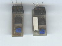
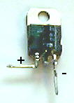
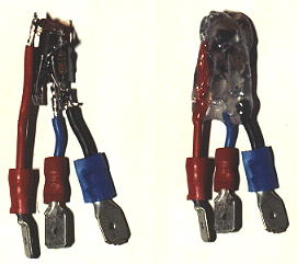
Simple Softstart
One time I wanted to integrate the electronics into the plug. But there
hasn't been enopugh place for the above mentioned circuits. Nevertheless
I wanted to have a soft startup. The switch (left picture) lets the voltage
above the slowly condensator rise which pulls the gate of the MOSFET high.
To get an immediate switch off (no additional power loss and long flashing)
the PNP transistor discharges the condensator immediately, if its base
isn't at positive voltage anymore. When the voltage of the condensator
drops below about 0,8V, the remaining discharge is accomplished by the
3 resistors R1 to R3. There is a vectorfile (47K
WMF-File) (all WMF-files as PDF) of
the graphic above available where you can really recognize something :-)
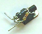
Of course it is possible to use the circuit with a switch in the main
current way (right picture). The BUZ11 is capable for up to 4A/50W. A higher
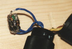
supply voltage also shouldn't be a problem. The construction was done in
form of a "hedgehog", which means the parts are mounted directly
and with few space onto the MOSFET. Everything is covered with hot glue
for isolation. So everything fits into a KSS plug from Devpein.
Here is a detailed plan how to build it.
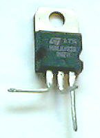 MOS-FET (Q1) |
 Capacitor(1uF) with plus
pole left Capacitor(1uF) with plus
pole left |
 PNP Transistor with flat
side down, Basis upwards. PNP Transistor with flat
side down, Basis upwards. |
 Resistor (R1) from GND to Basis. |
 R3 from Basis to input |
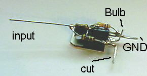 R2 from input to Gate (cut afterwards). |
For 6V R2 becomes 150kOhm. BUZ11 is exchanged with an BUZ12AL which
has less inner resistance
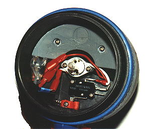
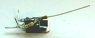
This is the finished circuit with cables, isolated with hot glue and
built into a Mares Arturo.
Simple anti-deep-discharge (6V)
 This
is an addition to simple 6V lights. If you use a zener-diode ZD with 3,3V
you get a cut-off voltage of about 4,3V and a hysteresis of about 0,8V.
The 6V high current relais takes the place of the resistor "Relais".
If you adjust the zener diode the circuit should work with 12V, too (R1
will be 3.3kOhm). The type of the ZD is irrelevant. Use any standard NPN
transistor for Q1 (e.g. BC547). V1 is the battery voltage after the main
switch. If the relais oszillates before switch-off a capacitor of 47uF
(10-100uF) between basis and emitter of Q1 might help.
This
is an addition to simple 6V lights. If you use a zener-diode ZD with 3,3V
you get a cut-off voltage of about 4,3V and a hysteresis of about 0,8V.
The 6V high current relais takes the place of the resistor "Relais".
If you adjust the zener diode the circuit should work with 12V, too (R1
will be 3.3kOhm). The type of the ZD is irrelevant. Use any standard NPN
transistor for Q1 (e.g. BC547). V1 is the battery voltage after the main
switch. If the relais oszillates before switch-off a capacitor of 47uF
(10-100uF) between basis and emitter of Q1 might help.
Attention ! This circuit won't warn you before switching off
!!!
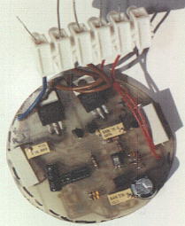
Microcontroller controlled electronics

That is a 6V 7Ah light from Multitec. When I bought it used, not working
at a diving base, the electronic was some prototype rubbish, which had
seen at least one short circuit. Same for the charger which I didn't used.
2 of the 5 cells were still working.
So I got new cells, changed the charging connector and built a new control
circuit.
At the inside there is a reed contact directly at the PCB, at the outside
a magnetic leverage with only one position.
I wanted to build a uC controlled circuit anyhow, so this was the chance.
Difficulties:
- 6V System(1), the uC should work below 5V because the voltage can drop under load.
- 6V System(2) MOS-FETs like more than 10V at the Gate to get a low resistance, at 6V I use logic level MOSFETs and two transistors in parallel. Another problem are the higher currents at 6V (35W 12V-3A 6V-6A)
- Only one switch position, but I wanted a dimmer.
For the switching positions I chose this system:
After first switch on the light goes to maximum brightness. If I switch
the lever to OFF for a short time(~100-500ms), the first dimm position
is used without switching off between. 2 times switching off gives the
second dimm position, more or less only an emergency light. 3 times ->
SOS Mode. The last two stages won't switch off when the battery goes down.
My first try had problems when the voltage dropped, so I had to add another chip. The circuit is working now, but it is not as simple as I intended it to be, so there are no plans until now.
DC-DC-converter
This simple circuit is useful if you want to charge an accumulator from a car battery.
Technical data DC-DC-converter:
- operating voltage: 6 - 18V
- output voltage: ca. 12 - 36V (2*Ue, depending upon input voltage and output current)
- output current: max. 0,5A (with appropriate cooling up to 2A).
My measurements: efficiency 80% at 1A
0A - 1,85 x Uein
1,4A - 1,4 x Uein
Charger (reconstruction)
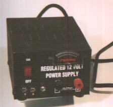 If
you need an inexpensive charger for lead-acid batteries, it is not necessary
to build everything on your own. There are a lot of power supplies available
which are prepared to give a voltage of 13,8V (for CB radios for example).
Most have current control already. That would be enough to charge a 12V
lead-acid battery.
If
you need an inexpensive charger for lead-acid batteries, it is not necessary
to build everything on your own. There are a lot of power supplies available
which are prepared to give a voltage of 13,8V (for CB radios for example).
Most have current control already. That would be enough to charge a 12V
lead-acid battery.
possible extensions (if needed and experience available):
- mostly there is a potentiometer on the printed circuit board to set the right voltage (see accus).
- The current is controlled with the help of a power resistance which is easy to find. If you change it (only larger) by switches you can charge batteries with different capacities, perhaps even NiCds with constant current.
- You can add a cheap amperemeter if none is built in to monitor the charging status.
- With some know-how it is possible to add switches for different voltages for batteries with built in diodes and others. 6V-usage isn't possible by this way.
Charger, as I want it (lead-acid)
I'm working on a charger especially for lead-acid batteries and travelling. (Yes I know there are some around right now!), which serves exactly my demands.
- 13,8 / 14,4 V / +0,6V / voltage adaption after current
- max. 1A (for 3,2/4Ah accu)
- charge control display with LEDs
- 110V/220V switchable
- As small as possible. Switching power supplies would be fine but building one is very complicated. Their advantages are not so relevant with this voltage/current characteristics.
Links
Basics | Simple electronic | Electronic for two bulbs | PWM | Simple Softstart | Simple anti-deep-discharge (6V) | Microcontroller controlled electronics | DC-DC-converter | Charger (reconstruction) | Charger, as I want it (lead-acid) | back to Homepage