Video housing by Mike Dolson
Email: Mike Dolson
Attached are the plans I drew up for my housing. I'm not an electronics
dude , so it is strictly a mechancical design.
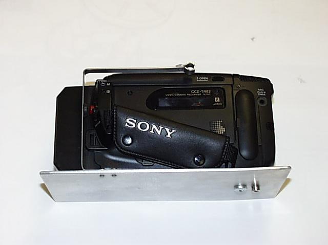
The specific location of each control is left off since I figured each
camera would be different.When I worked on the housing, the idea was to
put as few holes in it as possible, and to have no holes in the end plates.
Since these are the areas of greatest stress.
The drawings are in PDF format zipped into a file(283KB)
so they can be viewed with an Acrobat viewer available on the web.
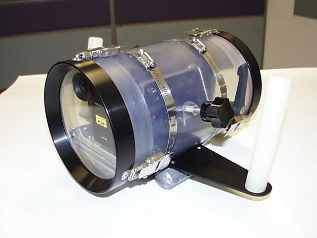
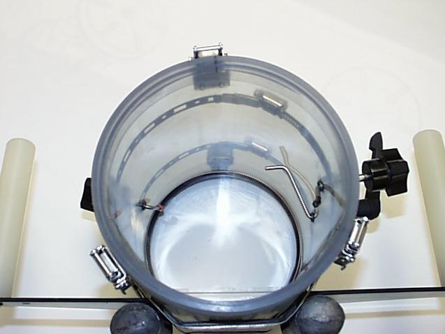
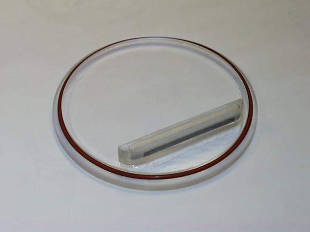
The main tube is 6 inch ID x 3/8 wall semi clear PVC extrusion. The ends were turned on a metal lathe, but the control gland holes were hand drilled 1/8 pilot hole then thru with correct drill for a 3/8-24 fine thread tap. The holes were counter sunk to remove any burs and provide a seal surface for the oring. The counter sink is a standard wood workers counter sink for flat head screws.
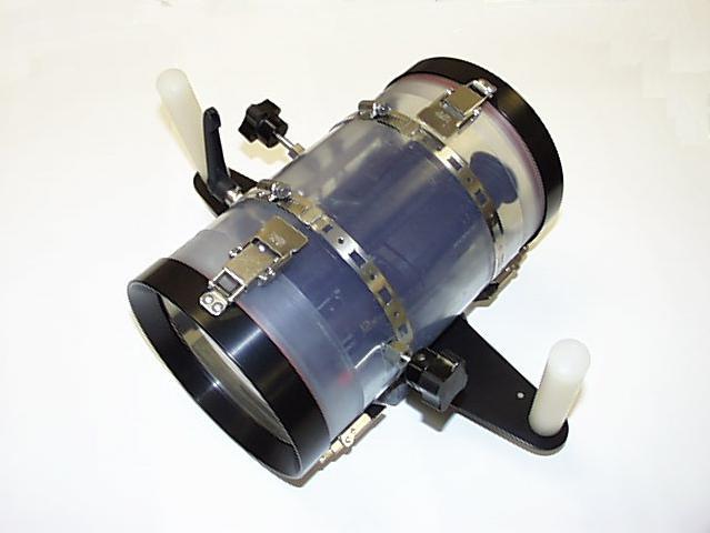
The control shafts are 1/4 dia stainless steel rod, turned down to 1/8 dia where I needed to bend them. The Glands are machined from 1/2 inch hex SS stock, and double oring sealed against the control shaft. The front and back lens plate are 1/2 ich acrylic with the camera tray supports solvent cemented on. The end rings are machined from 1 inch thick aluminum plate and black anodized.
The wing or handle support is 1/8 aluminum plate bent over a 1 inch pipe and machined V block in a large vise, also black anodized. It is a little flexible above water , I'd recommend 3/16 thickness. The ballast weights are 2 , 2lb bullet weights secured to the wing with 2 each countersunk stainless steel screws.
The spring latches, knobs and lever were all purchased from Reid Tool Supply Company catalog , Muskegon, Michigan 1-800-253-0421
Mike (and me too) has some more pictures, if someone is interested.